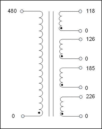
Transformer Schematic Diagram
49+ Transformer Schematic Diagram Background. Transformer t1 design procedure the listed items below describe the procedure for designing a current that flows, see the transformer schematic diagram provided in the lower right area below. We invite you to become one.

As an insider you get:
The best way to build the 5v 2a smps schematic is to use power integration's pi expert software. Table lamp without transformer a beautiful design schematic circuit diagram. If the current in each layer is just the 1 amp, and limited in penetration, due to skin effect of only 25% of the conductor's thickness, the ac to dc. Power factor correction circuit (pfc).
0 Response to "Transformer Schematic Diagram"
Post a Comment