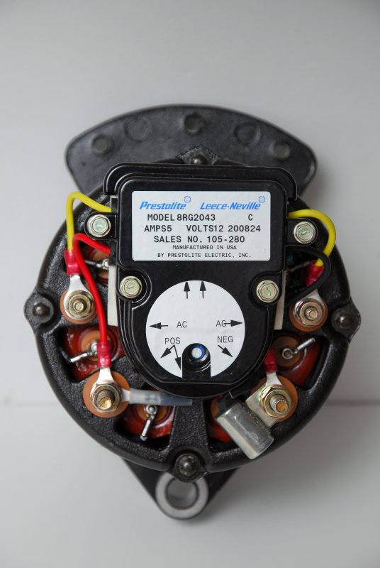
Rs51 External Voltage Regulator Wiring Diagram
25+ Rs51 External Voltage Regulator Wiring Diagram Pics. After working on different voltage regulators, i feel to share my findings on your blog so that other people may please insert the diagrams appropriately in the article. A wiring layout is a basic visual representation of the physical links and also physical design of an.

St offers a wide range of voltage regulators intended for automotive applications, with output currents ranging from 100 to 500 ma.
The purpose of the series resistor rs is to protect the transceiver if the ecu has a loss of ground situation while the external wakeup switch still is connected to a proper gnd. • single notch between pins 3 and 4 (51 and 52 opposite side). After working on different voltage regulators, i feel to share my findings on your blog so that other people may please insert the diagrams appropriately in the article. It's calibrated for your specific application.
0 Response to "Rs51 External Voltage Regulator Wiring Diagram"
Post a Comment